Channel Master Rotor Wiring Diagram

Electronic Master Remote Controlled Hdtv Antenna Ant3055

Pin On Technology

Structured Wiring Structured Wiring Home Automation Wire

Bobcat 753 Kopplingsschema Manuell Spara 15 0 Pa Bobcat 753

How To Connect Capacitor To Brushless Washing Machine Motor

Reading Hart Data Into Non Hart System Control System Reading
Antenna aerial rotator ar 300 ar301 ar 302 ar 303 channel master kerona masterrotor conrad duration.
Channel master rotor wiring diagram. Cosmetically the rotor is in nice condition without any cracks 2 of the cork feet on the bottom are missing. This is a channel master model number 9510. The channel master is a rotor that turns an antenna to adjust the television signal for the best reception. Channel master models class 2 wiring may be used.
View and download channel master 9521a owner s manual online. We have an automatic antenna rotor. You can connect a channel master model. Look in you instruction manual to see what wire size to use for longer runs.
9521a remote control pdf manual download. All channel master antenna rotors use 3 conductor rotor wire. Antenna rotator system instruction sheet hoja de instrucciones del sistema de rotación de antena feuille d instructions du système rotator de l antenne rotator drive unit installation. The channel master is a rotor that turns an antenna to adjust the television signal for the best reception.
Using this chart ensure that you have the proper gauge rotator cable based on the distance the control unit will be from the drive unit. Connecting the rotor is the process of wiring the base unit and the control unit to adjust the antenna from inside the house. For runs up to 200ft you can use 22ga 3 conductor wire. Amateur radio channel 14 318 views.
Connecting the rotor is the process of wiring the base unit and the control unit to adjust the antenna from inside the house. Programmable antenna rotator controller with infra red remote control.

Td 7059 Rotor Wiring Diagram Together With Channel Master Antenna

Pin On Newest Electronics

Arduino Gprs Weather Station Part 2 Upgraded Wind Sensors And

Clake One Clake Rear Brakes Brake Pedal Motorcycle Wiring
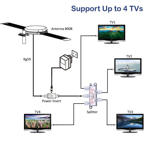
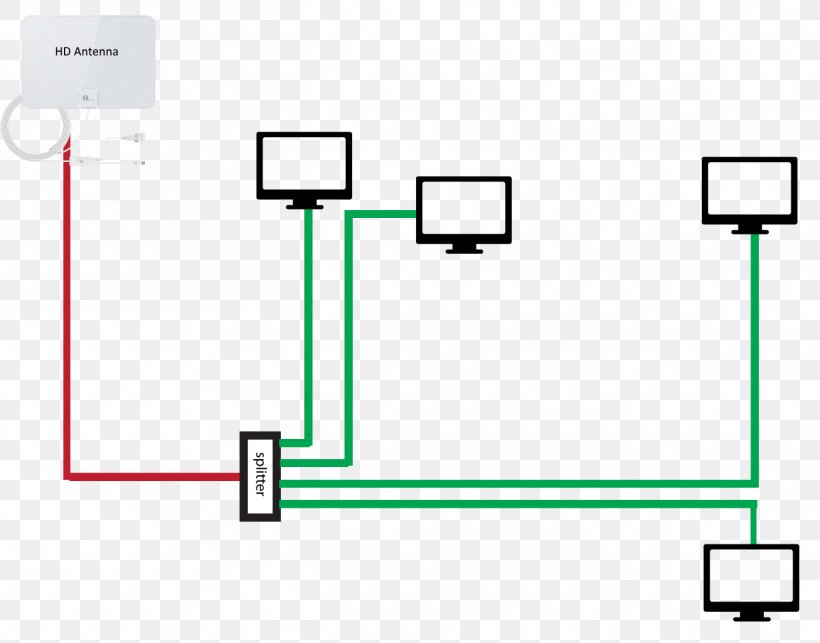
Wiring Diagram For Tv Antennas Outdoor Diagram Base Website
Aerials Television Antenna Antenna Rotator Wiring Diagram Cable

Ne 7772 Antenna Rotor Wiring Diagram Moreover Alliance Antenna

Wire Diagram Ford Starter Solenoid Relay Switch Mower
